http://searchdatacenter.techtarget.com/feature/The-case-for-a-leaf-spine-data-center-topology
The layered approach is the basic foundation of the data center design that seeks to improve scalability, performance, flexibility, resiliency, and maintenance

• Core layer—Provides the high-speed packet switching backplane for all flows going in and out of the data center. The core layer provides connectivity to multiple aggregation modules and provides a resilient Layer 3 routed fabric with no single point of failure. The core layer runs an interior routing protocol, such as OSPF or EIGRP, and load balances traffic between the campus core and aggregation layers using Cisco Express Forwarding-based hashing algorithms.
• Aggregation layer modules—Provide important functions, such as service module integration, Layer 2 domain definitions, spanning tree processing, and default gateway redundancy. Server-to-server multi-tier traffic flows through the aggregation layer and can use services, such as firewall and server load balancing, to optimize and secure applications. The smaller icons within the aggregation layer switch inFigure 1-1represent the integrated service modules. These modules provide services, such as content switching, firewall, SSL offload, intrusion detection, network analysis, and more.
• Access layer—Where the servers physically attach to the network. The server components consist of 1RU servers, blade servers with integral switches, blade servers with pass-through cabling, clustered servers, and mainframes with OSA adapters. The access layer network infrastructure consists of modular switches, fixed configuration 1 or 2RU switches, and integral blade server switches. Switches provide both Layer 2 and Layer 3 topologies, fulfilling the various server broadcast domain or administrative requirements.
This model scales somewhat well, but it is subject to bottlenecks if uplinks between layers are oversubscribed. This can come from latency incurred as traffic flows through each layer and from blocking of redundant links
Leaf-spine data center architectures
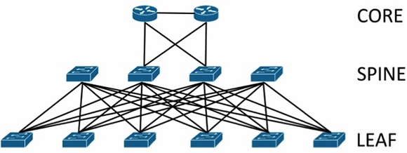
Inmodern data centers, an alternative to the core/aggregation/access layer network topology has emerged known asleaf-spine. In a leaf-spine architecture, a series ofleafswitches form the access layer. These switches are fully meshed to a series ofspineswitches.Leaf-spine designs are pushing out the hierarchical tree data center networking model,
The mesh ensures that access-layer switches are no more than one hop away from one another,minimizing latency and the likelihood of bottlenecksbetween access-layer switches. When networking vendors speak of anEthernet fabric, this is generally the sort of topology they have in mind.
Leaf-spine architectures can belayer 2orlayer 3, meaning that the links between the leaf and spine layer could be eitherswitchedorrouted. In either design, all links are forwarding; i.e., none of the links are blocked, since STP is replaced by other protocols.
In a layer 2 leaf-spine architecture, spanning-tree is most often replaced with either a version ofTransparent Interconnection of Lots of Links(Trill) orshortest path bridging(SPB). Both Trill and SPB learn where all hosts are connected to the fabric and provide a loop-free path to their Ethernet MAC addresses via a shortest path first computation.
Brocade's VCS fabric and Cisco's FabricPath are examples of proprietary implementations of Trill that could be used to build a layer 2 leaf-spine topology. Avaya's Virtual Enterprise Network Architecture can also build a layer 2 leaf-spine but instead implements standardized SPB.
In a layer 3 leaf-spine, each link is a routed link.Open Shortest Path Firstis often used as the routing protocol to compute paths between leaf and spine switches. A layer 3 leaf-spine works effectively when network virtual local area networks are isolated to individual leaf switches or when a network overlay is employed.
